华为

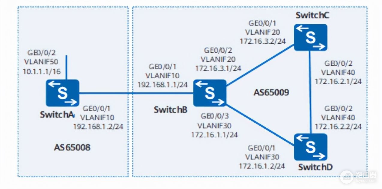
1)配置各接口所属的VLAN。
#配置switchA。
system-view
sysname switchA
vlan batch 10 50
interface gigabitethernet 0/0/1
port link-type trunk
port trunk allow-pass vlan 10
quit
interface gigabitethernet 0/0/2
port link-type trunk
port trunk allow-pass vlan 50
quit
#配置switchB。
system-view
sysname switchA
vlan batch 10 20 30
interface gigabitethernet 0/0/1
port link-type trunk
port trunk allow-pass vlan 10
quit
interface gigabitethernet 0/0/2
port link-type trunk
port trunk allow-pass vlan 20
quit
interface gigabitethernet 0/0/3
port link-type trunk
port trunk allow-pass vlan 30
quit
switchC和switchD的配置与switchB类似,不再赘述。
2)配置各vlanif接口的IP地址。
#配置switchA。
interface vlanif 10
ip address 192.168.1.2 24
quit
interface vlanif 50
ip address 10.1.1.1 16
quit
#配置switchB。
interface vlanif 10
ip address 192.168.1.1 24
quit
interface vlanif 20
ip address 172.16.3.1 24
quit
interface vlanif 30
ip address 172.16.1.1 24
quit
switchC和switchD的配置与switchB类似,不再赘述。
3)配置IBGP连接。
#配置switchB。
bgp 65009
router-id 172.17.2.2
peer 172.16.1.2 as-number 65009
peer 172.16.3.2 as-number 65009
quit
#配置switchC。
bgp 65009
router-id 172.17.3.3
peer 172.16.3.1 as-number 65009
peer 172.16.2.2 as-number 65009
quit
#配置switchD。
bgp 65009
router-id 172.17.4.4
peer 172.16.1.1 as-number 65009
peer 172.16.2.1 as-number 65009
quit
4)配置EBGP。
#配置switchA。
bgp 65008
router-id 172.17.1.1
peer 192.168.1.1 as-number 65009
quit
#配置switchB。
bgp 65009
peer 192.168.1.2 as-number 65008
quit
#查看BGP对等体的连接状态。
display bgp peer
5)配置switchA发布路由10.1.0.0/16。
#配置switchA发布路由。
bgp 65008
ipv4-family unicast
network 10.1.0.0 255.255.0.0
quit
#查看switchA,switchB和switchC的路由表信息。
display bgp routing-table
6)配置BGP引入直连路由。
#配置switchB。
bgp 65009
ipv4-family unicast
import-route direct
quit
#查看switchA和switchC的路由表。
#在switchC上使用ping进行验证。
ping 10.1.1.1
注意:在该场景中互联接口的STP处于未使能状态,因为在使能STP的环形网络中,如果交换机的vlanif接口构建三层网络,会导致某个端口被阻塞,导致三层业务不能正常运行。
H3C

1)配置各vlanif接口的IP地址。
#配置switchA。
system-view
interface vlan-interface 100
ip address 8.1.1.1 255.255.255.0
quit
interface vlan-interface 200
ip address 3.1.1.2 255.255.255.0
quit
interface loopback 0
ip address 1.1.1.1 255.255.255.255
quit
switchB和switchC配置和switchA类似,不再赘述。
2)配置IBGP连接。
- 为了防止端口状态不稳定引起路由震荡,使用loopback接口来创建IBGP对等体。
- 使用loopback接口创建IBGP对等体时,因loopback接口不是两个对等体的实际连接口,所以,必须使用peer connect-interface命令将loopback接口配置为BGP连接的源接口。
- 在AS 65009内部,使用OSPF协议,保证switchB和switchC的loopback相互之间路由可达。
#配置switch B。
system-view
bgp 65009
router-id 2.2.2.2
peer 3.3.3.3 as-number 65009
peer 3.3.3.3 connect-interface loopback 0
address-family ipv4 unicast
peer 3.3.3.3 enable
quit
ospf 1
area 0
network 2.2.2.2 0.0.0.0
network 9.1.1.0 0.0.0.255
quit
#配置switch C。
system-view
bgp 65009
router-id 3.3.3.3
peer 2.2.2.2 as-number 65009
peer 2.2.2.2 connect-interface loopback 0
address-family ipv4 unicast
peer 2.2.2.2 enable
quit
ospf 1
area 0
network 3.3.3.3 0.0.0.0
network 9.1.1.0 0.0.0.255
quit
#查看IBGP对等体信息。
display bgp peer ipv4
3)配置EBGP连接。
- EBGP邻居关系的两台路由器,处于不同的AS域,对端的loopback接口一般路由不可达,所以一般使用直连地址建立EBGP邻居。
#配置switchA。
system-view
bgp 65008
router-id 1.1.1.1
peer 3.1.1.1 as-number 65009
address-family ipv4 unicast
peer 3.1.1.1 enable
network 8.1.1.0 24
quit
#配置switchB。
system-view
bgp 65009
peer 3.1.1.2 as-number 65008
address-family ipv4 unicast
peer 3.1.1.2 enable
network 8.1.1.0 24
quit
#查看switchB的BGP对等体的连接状态。
display bgp peer ipv4
#查看switchA、switchB和switchC的BGP路由表。
display bgp routing-table ipv4
4)配置BGP引入直连路由。
#配置switchB。
bgp 65009
address-family ipv4 unicast
import-route direct
quit
#查看switchA和switchC的BGP路由表。
display bgp routing-table ipv4
#使用ping进行验证。
ping 8.1.1.1
锐捷

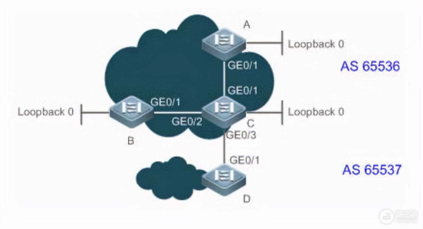
1)配置接口IP地址。
#配置A。
configure terminal
interface loopback 0
ip address 10.1.1.1 255.255.255.255
exit
interface gigabitethernet 0/1
ip address 192.168.1.1 255.255.255.0
exit
router bgp 65536
neighbor 10.1.1.3 remote-as 65536
neighbor 10.1.1.3 update-source loopback 0
配置B和配置A类似,不再赘述。
#配置C。
configure terminal
interface loopback 0
ip address 10.1.1.3 255.255.255.255
exit
interface gigabitethernet 0/1
ip address 192.168.1.3 255.255.255.0
exit
interface gigabitethernet 0/2
ip address 192.168.2.3 255.255.255.0
exit
interface gigabitethernet 0/3
ip address 192.168.3.3 255.255.255.0
exit
router bgp 65536
neighbor ibgp-group peer-group
neighbor ibgp-group remote-as 65536
neighbor ibgp-group update-source loopback 0
neighbor 10.1.1.1 peer-group ibgp-group
neighbor 10.1.1.2 peer-group ibgp-group
neighbor 192.168.3.4 remote-as 65537
#配置D。
configure terminal
interface gigabitethernet 0/1
ip address 192.168.3.4 255.255.255.0
exit
router bgp 65537
neighbor 192.168.3.3 remote-as 65536
#使用show命令查看BGP邻居状态。
show ip bgp neighbor

